
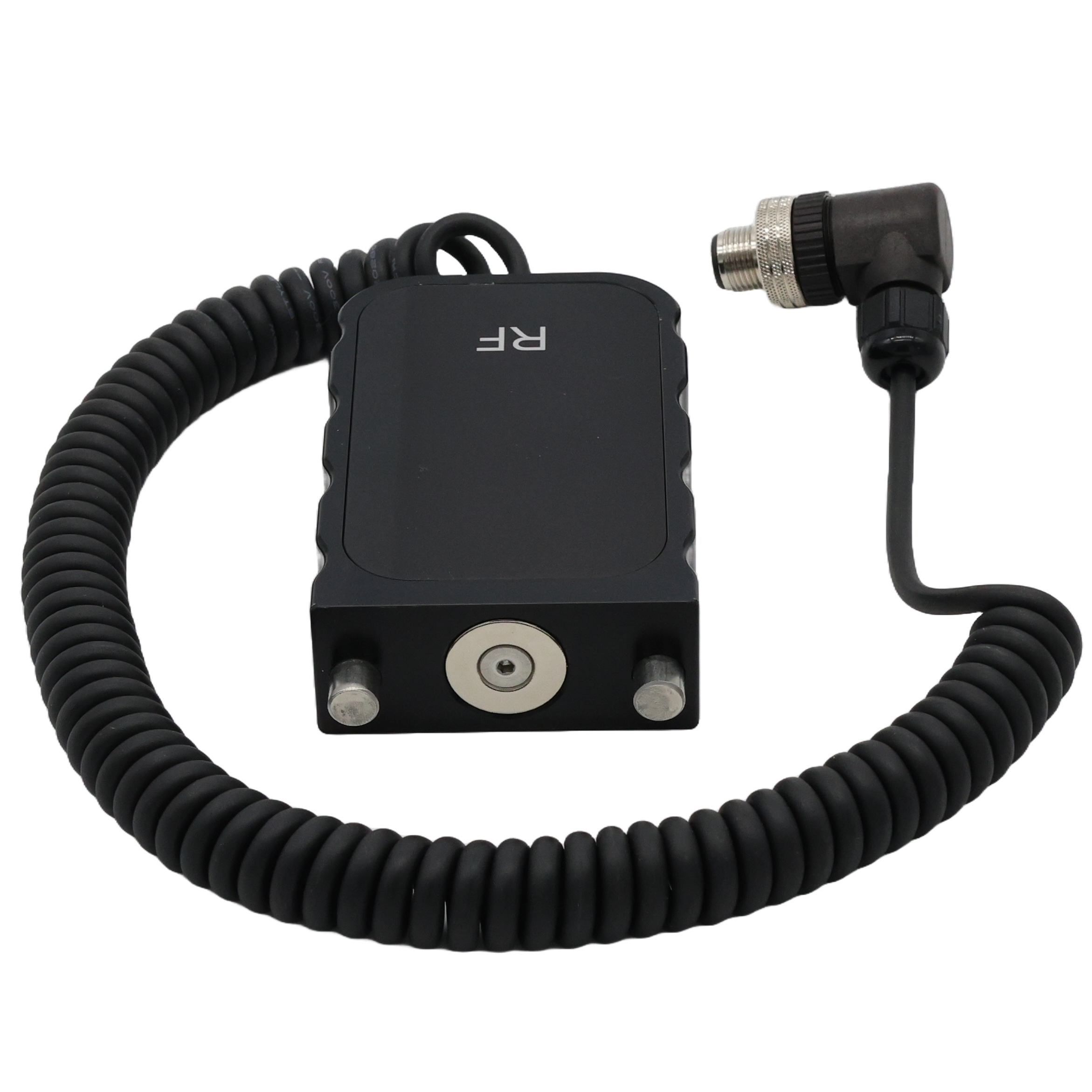
Camber Gauges: Where the Number Comes From and Where the Error Does
Camber is an angle between two references. One reference is vertical, and vertical is always gravity: every camber gauge, from a $40 bubble vial to a camera-based shop rack to a high-end MEMS inclinometer, ultimately reads against the local gravity vector. The other reference is the wheel, or more precisely, whatever surface your gauge actually touches and treats as the wheel. Since the vertical side is settled physics, every camber measuring tool ever sold is really an answer to one question: what are you using for the wheel?
This article walks through the common gauge types with their honest pros and cons, explains what an alignment rack's compensation routine is really doing and why it exists at all, and then follows the error to its actual sources.
What every camber gauge measures
On the vertical side, a bubble vial or a MEMS inclinometer reads its own tilt relative to gravity. The gauge measures the wheel against true vertical while the car's suspension responds to the floor it sits on. If the floor tilts, the chassis tilts with it, and every camber reading now contains the floor. More on that below, because it is one of the two dominant error sources in garage alignments.
On the wheel side, the gauge has to touch something and call it the wheel plane. The candidates are the rim lips, the tire sidewalls, the wheel face, or the hub itself. They are not equivalent, and the differences between them are the second dominant error source.
The gauge types
Bubble vial gauges
The classic motorsport pattern: a rigid frame with two or three contact feet that register on the rim lips, and one or more curved bubble vials calibrated in degrees, sold in fixed-width and adjustable-width versions for decades.
- Pros: no batteries. Rugged enough to live in a trailer. The good ones resolve to roughly a quarter degree by eye and repeat well when the same person uses them the same way. Cheap enough that every crew member can have one.
- Cons: quarter-degree resolution is an order of magnitude coarser than the tolerance windows on modern performance cars. Reading a bubble edge against graduations is interpretive, and two people will read the same vial differently. Adjustable frames add joints, and every joint is a place the geometry can shift. And the feet sit on the rim lips, which means the gauge inherits every problem with the wheel as a reference.
Vision systems (imaging alignment racks)
A modern imaging alignment rack clamps a target to each wheel and watches all four with cameras. It measures camber, caster, and toe simultaneously, referenced to the rack surface and to the car's own thrust line, using a substantial stack of math and assumptions to get from camera images to alignment angles. It is accurate equipment when installed, calibrated, and operated correctly.
But look closely at the procedure every rack requires before it will show you numbers: rolling compensation. The technician rolls the car back several inches and forward again while the cameras track each target through the wheel's rotation. The software fits the motion, finds the wheel's true axis of rotation, and mathematically subtracts the difference between that axis and the plane of the clamped target.
The target is clamped to the wheel, and the wheel's outer surfaces are unreliable as a reference. The entire compensation procedure exists to remove the wheel from the measurement and recover the spindle axis behind it.
- Pros: measures everything at once, referenced to a common plane. Fast in a shop workflow, and the printout carries weight with customers.
- Cons: the accuracy is conditional. The rack must be level and periodically calibrated, the slip plates must be free, the clamps must not have shifted during the roll, and the car must be re-settled after rolling. Skipped or lazy compensation puts the full wheel error right back into the numbers, and the confident four-decimal printout gives no hint that it happened. Racks are also stationary and shop-priced: none of this exists in the paddock. A rack is only as good as the discipline of the person running it, which is exactly the dependency a measurement system is supposed to remove. Racks will commonly display resolution (digits) well past what they are accurate to.
Basic digital gauges (off-the-shelf MEMS)
The bubble frame concept with an off-the-shelf MEMS inclinometer instead of a vial. The generic sensors in these gauges read in 0.1 degree steps with rounding, so the display alone can sit a twentieth (0.05) of a degree from the truth before it rounds up or down.
The extreme end of off-the-shelf is the phone in your pocket. The IMU inside a phone exists to flip your screen and steer video games. It is an orientation sensor, not a measurement instrument, with no true calibration path, no accuracy spec, and firmware that filters and smooths readings in ways an app cannot see around. Add a case, screen glass, and a camera bump between the sensor and the wheel and nothing registers repeatably. Treat it as a plus or minus half degree tool and it will not disappoint you.
- Pros: digital display, no interpretive reading, and a calibration routine that lets you cancel a known reference surface before measuring. Faster than a bubble for repeated left-right comparisons. Some models hold a reading, which helps when the gauge position blocks your view.
- Cons: these gauges display resolution well beyond their accuracy. A screen showing 0.1 or even 0.01 degree steps says nothing about calibration error, zero drift with temperature, or cross-axis sensitivity, and most manufacturers will not publish an accuracy spec. When a spec sheet lists resolution and goes quiet about accuracy, that silence is the spec. Batteries die at the track. If using a wheel mount, a digital readout o is a precise report of an imprecise thing.
Advanced digital gauges (custom high-precision MEMS)
The same physics, built to instrument standards. A custom high-precision MEMS inclinometer is individually calibrated, temperature compensated, and characterized across its working range. It resolves to 0.01 degrees or finer, and the accuracy is stated in writing rather than implied by the display.
- Pros: the sensor stops being part of the error budget. The rule for any electronic gauge is that the sensor's stated accuracy, not its display resolution, should be tighter than the window you are measuring to. If you need to hit a 3 arc minute factory tolerance, you need a sensor accurate beyond it, and this is the only tier that can honestly claim that.
- Cons: Priced accordingly. A high-precision sensor clamped to a wheel lip is still measuring the wheel. This tier only pays off when it is paired with a reference worthy of it.
Why the wheel is the wrong reference
Time to quantify the thing every section above kept deferring.
A wheel is not a reference surface. It is a structural component with manufacturing tolerances, and it lives a hard life. The bead seats and the cosmetic rim lips are formed and machined surfaces, but they are not held square to the mounting face to anything like instrument tolerance, because they do not need to be. The tire hides everything. The accepted tolerances say it plainly: NHTSA allows up to 0.75 millimeters of runout on aluminum wheels and 1.25 millimeters on steel, and a wheel is considered ideal within 0.5. By measurement standards, that is a ton.
Now put a camber gauge's feet on those lips. On a 20 inch wheel the contact points span roughly 480 millimeters. Half a millimeter of lateral runout, the ideal wheel, tilts the measured plane by about 3.6 arc minutes, call it 0.06 degrees. Read that against the factory windows: the GT4 RS specifies front camber inside a 3 arc minute tolerance with left and right matched within 3. A wheel well inside accepted tolerance, an ideal one, induces error that consumes the entire factory window before the gauge measures anything.
And runout is only the start of the wheel's contributions:
- Clock position. Runout is a rotating error. Measure at one wheel position, rotate the wheel half a turn, and the runout contribution flips sign. This is also the fix: measure, rotate 180 degrees, average the two readings, and runout cancels. Almost nobody does this with a hand gauge, because rotating the wheel means lifting the corner, which unsettles the suspension you just spent ten minutes settling.
- Mounting variance. Adjustable frame gauges register wherever the feet land: on paint, on polish marks, on the tiny lip differences between wheel designs. Move the feet a few millimeters and the reading moves. Different crew members place feet differently, which is why "the gauge repeats for me" and "the gauge repeats" are different claims.
- Rim condition. Curb rash and bent lips sit exactly where the gauge feet want to sit.
- The tire. Gauges and adapters that touch the sidewall reference a rubber surface whose bulge changes with pressure, temperature, and load.
The hub does not have any of these problems. The hub flange and rotor face are machined square to the spindle axis because the car does not work otherwise. Every wheel-referenced method is an attempt to estimate, through the wheel, the orientation of a machined surface sitting two inches behind it.
Where the rest of the error comes from
Suppose the wheel side were perfect. The state of the car and the instrument itself still carry the rest of the error budget.
The floor. A gravity-referenced gauge reads the wheel against true vertical, but the chassis leans with the floor. Garage floors are legally required to slope for drainage, commonly around one percent, which is 0.57 degrees. Cross slope tilts the whole car, adding to the camber reading on one side and subtracting on the other, in the same direction, which makes left to right matching within 0.1 degrees physically impossible to verify on that floor. This single error source is larger than every difference between gauge brands combined. Leveling the contact patches, with plates, shims, or a surveyed pad, is not a nicety. It is the other half of the measurement.
The chassis state. Camber is a function of suspension position. A car that has not settled after being rolled or jacked, a car with anti-roll bars still connected and preloaded, a car without driver ballast or at the wrong fuel load, is a car whose camber is different from its on-track camber by amounts greater than gauge precision. The measurement discipline in our setup guides, settle the car, bars off, ballast in, exists because no instrument can fix a wrong chassis state.
The instrument, last and least when it is chosen correctly. Vial calibration, MEMS zero drift with temperature, resolution rounding. Real, worth checking against a known surface periodically, and the smallest slice of the total error, provided the sensor's accuracy genuinely exceeds the window you are measuring to. The error stack, in order of size: floor and chassis state first, wheel reference second, instrument last.
Measuring from the hub
That is the entire premise of the hub stand. Pull the wheel, mount the stand to the hub flange and set the car down at ride height on the stands. The wheel, its runout, its curb history, and its clock position leave the measurement completely, not compensated for, but deleted. Camber is now read from a machined surface rigidly registered to the spindle axis, on a suspension sitting at its working position, and the same reading repeats regardless of who takes it, because there is no foot placement to vary and no bubble to interpret.
The sensor matters here too, and it should outclass the job. The MEMS sensors in IntelAlign read internally to 0.001 degrees and are accurate to 0.02 degrees, comfortably beyond the tightest factory camber windows, with the accuracy specified rather than implied. That is what "a sensor beyond the needed accuracy" looks like in practice: the instrument's entire error budget fits inside the tolerance you are trying to hit, so the numbers you read are the car, not the tool.
The floor gets solved the same way the wheel did: directly. Leveling feet under each stand, leveling vials to verify, and a laser level to put all four contact patches in a single plane, so the gravity reference and the surface the car sits on agree. With both references handled, IntelAlign displays live camber per corner on the iPad while you adjust, left and right side by side, the number moving in real time as the wrench turns instead of an adjust, remeasure, repeat loop.
The tool that removed the wheel is the same tool holding the corner at ride height, so the reference problem and the suspension-position problem are solved by the same piece of hardware.
The big picture
True accuracy, numbers inside a modern factory tolerance that repeat across crew members and sessions, is not one tool. It is three conditions met at once: a sensor accurate beyond the window you are measuring to, not one that merely displays enough digits; a hub-mounted reference, so the wheel and its runout never enter the measurement; and low-friction support under the car, so the suspension settles to its true working position instead of the position friction left it in. Miss any one and the other two cannot save you. A perfect sensor on a wheel lip is a precise report of runout. A hub reference on a bound suspension measures the right surface in the wrong position. A settled car read by an uncertified sensor is a guess with a confident display. All three together is what measurement-quality means.
This guide is published by CSM Performance. We design and manufacture precision alignment and setup tooling used by pro race teams, performance shops, and serious owners running these cars at the limit. If you're building out an alignment capability at home, in a shop, or in the paddock, reach out: info@csmperformance.com


Share:
Scale Pads and Load Cells
Camber Deep Dive