
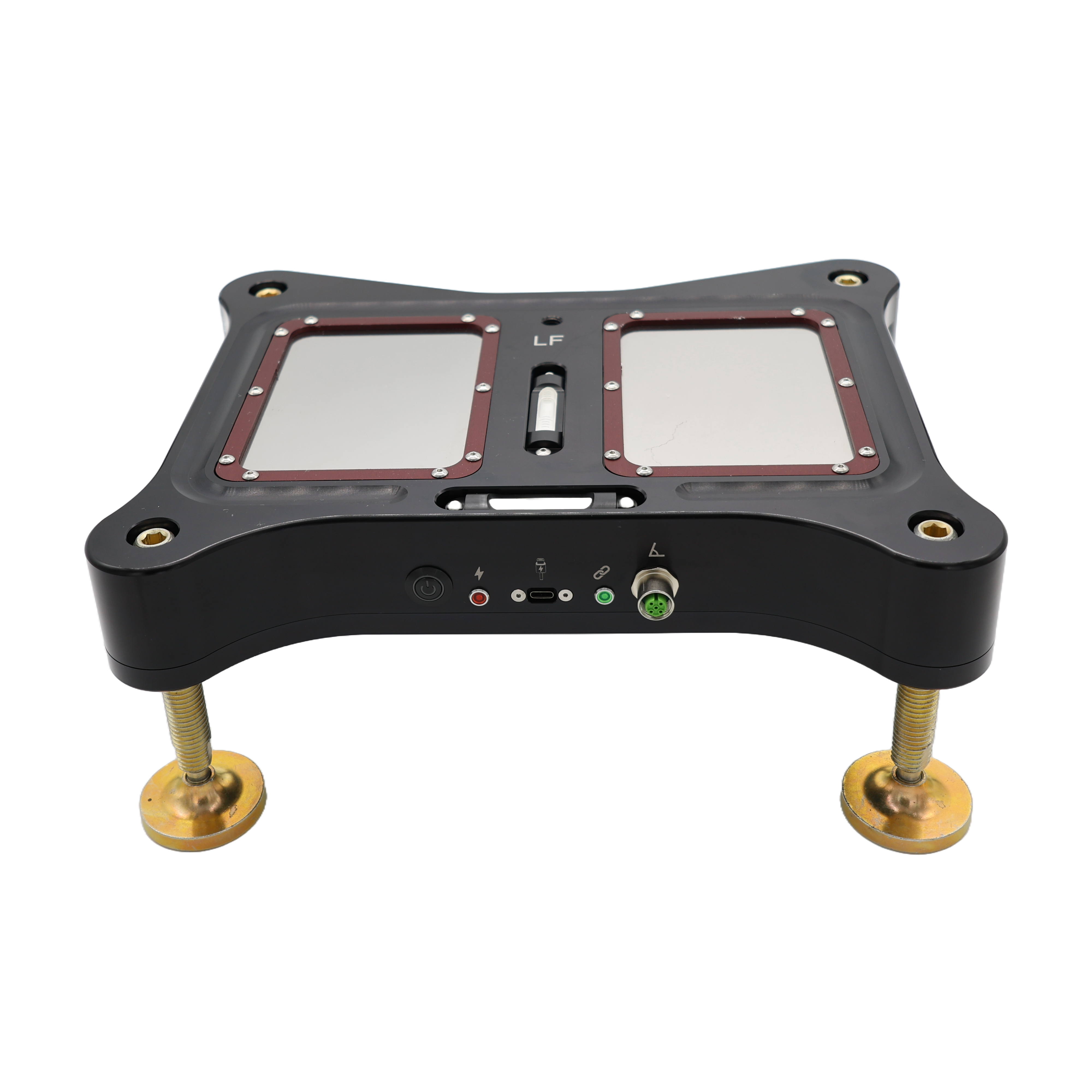
Corner balancing is a measurement problem before it is a tuning problem. Cross weight is calculated from four separate readings, which means the scales themselves have to be trustworthy to a fraction of a percent, corner to corner, or you are adjusting spring perches to chase noise. This article covers the load cell technologies that do the measuring, how those cells get arranged inside a scale pad, how they get integrated into hub stands, and why some of those architectures are worth trusting and some are not.
What a scale pad actually is
Strip the branding and a scale pad is three things: a platform stiff enough to carry a wheel, one or more load cells that convert force into an electrical signal, and electronics that turn that signal into a number. The weight on the display is not a direct measurement of mass. It is a voltage, measured in millionths of a volt, amplified, digitized, filtered, and scaled by a calibration factor stored in memory. Every link in that chain is a place where quality shows up, or doesn't.
Types of load cells
Essentially every electronic corner weight scale worth discussing is built on strain gauge load cells. A strain gauge is a thin foil resistor bonded to a machined metal element, usually aluminum or alloy steel. Load the element and it deflects; how much it deflects depends on the type of load cell. The foil stretches with the element and its resistance changes. Wire four gauges into a Wheatstone bridge and you get a voltage output proportional to load, with the bridge arrangement canceling much of the error that any single gauge would produce on its own. Within the strain gauge family, the shape of the machined element defines the cell's character.

Shear point (shear beam) cells. A machined bar, fixed at one end and loaded at the other, with the gauges reading shear strain in a machined web rather than bending strain at the surface.
- Pros: almost no deflection under load, good tolerance of load position along the beam, good side load rejection, robust and widely available in matched sets.
- Cons: must be loaded perpendicular to the mounting face to read true, needs proper load introduction hardware, one cell alone cannot serve a whole platform, so designs using them need multiples.
Single point cells. An element machined with internal parallelogram flexures so the output stays constant even when the load lands off-center. The geometry itself compensates.
- Pros: one cell can serve an entire platform, which makes it the cheapest way to build an accurate scale pad. Genuinely insensitive to where the tire sits on the pad, within its rated platform size.
- Cons: substantially more deflection than a shear point design, lower capacity headroom, and less tolerance for overload and shock. The deflection matters more than most spec sheets admit, for reasons covered below.
Canister and pancake compression cells. Cylindrical elements loaded in pure compression through a defined seat or load button.
- Pros: high capacity, excellent stability and accuracy, the standard in industrial and calibration-grade weighing.
- Cons: cost, height, and a hard requirement for well-designed load introduction that guarantees force enters vertically. Rare in portable motorsport scales for those reasons.
Types of scale pads: how the cells are arranged
The cell is half the story. How the pad's designer arranges cells under the platform is the other half, and it is where the price differences between pads actually come from.
Four-cell pads. A cell at or near each corner of the platform, outputs summed in a junction circuit. This is the professional architecture, typically built on shear point elements.
- Pros: the summed output is inherently insensitive to where the tire sits. Load is shared four ways, so each cell operates low in its range where linearity is best. With shear point cells, platform deflection is minimal. Corner matching can be trimmed in the junction.
- Cons: four cells per pad means sixteen per car, which is why these pads cost what they cost. Four cells also means four things that must be matched and compensated together; a cheap four-cell pad with unmatched cells is worse than a good single point pad.
Single point pads. One cell under the center of the platform, the pad equivalent of a quality shipping scale.
- Pros: the affordable path to genuine accuracy. Off-center compensation is built into the cell geometry, so a well-executed single point pad reads honestly anywhere on the platform.
- Cons: all the load goes through one element, so the pad deflects under the wheel, and the deflection is not cosmetic. Worse, the deflection depends on where the tire sits. The cell's compensation corrects the reading for off-center load, but it does nothing about the physics: load the platform away from center and it cantilevers over the single element, deflecting further and tipping slightly compared to a centered load. So the amount each corner sinks depends not just on the weight it carries but on where the tire happened to land on the pad. Each corner of the car carries a different weight, so each pad sinks by a different amount, and the car ends up sitting lower on one corner than another. That height difference cross-loads the chassis through its own springs, which redistributes weight between the corners and corrupts the very corner weights you are trying to read. Capacity and overload margins are also tighter, and the platform itself must be stiff, because the cell's compensation assumes a rigid plate above it.
Cheap multi-sensor pads. Consumer-grade half-bridge sensors at the corners, the architecture inside bathroom scales, occasionally dressed up in an anodized housing.
- Pros: cheap.
- Cons: half-bridge sensors give up most of the Wheatstone bridge's error cancellation, matching is poor, temperature behavior is poor, and the housings flex. If a set of four pads costs less than one quality load cell, this is what is inside.
The specs that matter once the architecture is right
Resolution is not accuracy. A display that reads in 0.1 lb increments tells you about the analog-to-digital converter, not about the measurement. Plenty of pads resolve 0.1 lb and are only accurate to several pounds. The specs that matter are accuracy as a percentage of applied load and corner-to-corner matching across the set. The standard for quality corner weight scales is accuracy within 0.1% of full scale, and it's worth understanding what that figure actually is: a combination of hysteresis, non-linearity, and non-repeatability. Each of those error sources is individually below 0.1%, but by the time you stack them up the total lands around 0.1%. Keep that stack in mind. It becomes important later.
Temperature compensation is where budget cells cut the corner. Strain gauge output shifts with temperature. The element expands, the gauge factor changes, the bridge drifts. Quality cells are individually compensated with matched resistors across a stated range. Even with good compensation, it is normal for cells to need a re-tare, a fresh zero, after a large temperature swing; that is routine hygiene.
Deflection corrupts two measurements at once. Any deflection in the pad, whether from a flexing platform or a high-deflection cell design, creates two separate problems. First, it corrupts the corner weights themselves: a deforming platform steers force into the cells at angles they were never calibrated for, and the four corners rarely deflect by the same amount. Second, it corrupts ride height. A car sitting on pads that sink under load is not sitting at the height you think it is, and if each corner sinks differently, every ride height measurement taken on the scales carries that error. Shear point cells have almost no deflection, which is exactly why they anchor the best designs.
The errors that aren't inside the pad at all
The best load cell ever made cannot fix pads sitting at different heights: raise one pad relative to the others and you have cross-jacked the car through its own springs, exactly like turning a spring perch. The pads do not need an elaborate ritual; they need to be leveled and put in the same plane, and it doesn't matter how you get there. Shims, leveling feet, a dedicated leveling system, whatever your floor demands. Check it before every session. This is precisely the problem grid plates and leveling systems exist to solve.
And then there is bind. The car has to settle to true ride height before any corner weight means anything, and rubber on a scale surface fights settling. The contact patch grips the pad and the suspension binds against it every time you make an adjustment. On the ground you roll the car back and forth to break the friction. On scales, you can't. Bouncing the corners helps and doesn't fully solve it; roll-off ramps and re-rolls are slow and still approximate. The friction between tire and pad is a structural limitation of weighing through the wheel, the same way wheel runout is a structural limitation of aligning off the rim.
Load cell integration with hub stands
Regular readers know where this goes. Hub stands ride on ball transfers over hardened plates, so the corner floats and the suspension settles itself continuously: no rolling, no bind. Putting load cells into that system is what turns a settled corner into a trustworthy corner weight. There are several ways to do it, and they are not all equal.
Hub stands on top of conventional scales. The entry point: set your existing scale pads under the stands and weigh through them.
- Pros: uses hardware you may already own, and the suspension still settles freely on the ball transfers above the pad, so the bind problem is solved even though the scales are conventional. Corner weights on a genuinely settled suspension are already better than corner weights on bound tires.
- Cons: the stack gets tall, and every interface in that stack (floor, pad, stand base) is another surface that has to be flat, level, and coplanar with the other three corners. The pad also carries the stand's feet rather than a tire's contact patch, so platform stiffness under concentrated loads matters more than the pad's designer assumed. And if the pads underneath are single point designs, their deflection joins the stack: each corner sinks by a different amount under its different load, the stand heights move with the pads, and the corner-to-corner height differences that corrupt corner weights on a plain single point pad now corrupt them here too. Workable, but it is two products doing one job.
The worst integration: ball transfers connected directly to the load cells. There is a tempting shortcut in the hub stand architecture: thread the ball transfers straight into the load cells, two shear point cells per stand with the transfers threaded directly into them. It is mechanically elegant. It is also fighting the physics of how those cells work.
Shear point load cells are designed to be loaded perpendicular to their mounting face. Nothing else. But a hub stand bolts to the hub, which means the stand leans with the wheel's camber angle, and the load arrives at whatever angle the suspension dictates. At 4 degrees of camber, the cell sees the load at 86 degrees instead of 90. That does two things at once. The vertical component the cell measures drops by about 0.24%, which by itself is 2.4 times the entire 0.1% accuracy standard, before hysteresis, non-linearity, and non-repeatability have taken their share. And a side load equal to roughly 7% of the wheel load gets driven through the cell in a direction it was never designed to measure. With negative camber, that side load compresses the cell along its length. Side load sensitivity shows up as false vertical signal, and it varies unit to unit, so no two stands lie by the same amount.
The ball transfer itself makes it worse, because it acts as a lever arm. At zero camber it has no effect. As camber is added, the load is no longer applied along the cell's neutral axis; it is applied down at the ball transfer, so the cell also sees a bending moment. That moment can be a bigger error source than the side force itself. And here is the part that closes the door on any easy fix: the error scales with both camber angle and corner weight, so it changes car to car and corner to corner. You cannot calibrate it out with a fixed factor, because there is no fixed condition to calibrate against.
- Pros: fewest parts, lowest build cost.
- Cons: everything above. In our own testing, off-axis loading like this produced large inaccuracies, for exactly the reasons described.
 The next best: a single point cell in the measuring base. Put the cell below the ball transfers, in a base that stays flat on the ground, and the camber problem largely disappears: the plate still deflects depending on the position of the Hub Stands.
- Pros: one cell per corner, off-center compensation built into the cell, and the load path stays correct regardless of camber.
- Cons: the single point cell's deflection, which now shows up directly as ride height error at the hub and corner weight error from the deflection with the car no longer sitting in the same plane.
The best integration: four shear point cells in the measuring base. This is what we use. Same principle as the professional four-cell scale pad, applied under the ball transfers: the transfers ride on their own rigid structure, that structure is carried on four shear point cells, and the cells sit flat to the ground where the load reaches them purely vertically, at any camber angle, at any corner weight. The leveling feet thread directly into the cells, so the same hardware that puts all four corners in the same plane also guarantees the load enters each cell exactly where and how it was designed to be loaded.
- Pros: the summed four-cell output is insensitive to where the stand loads the plate. Shear point elements have almost no deflection, so hub-referenced ride heights stay true while you weigh. Each cell runs low in its range where linearity is best. Camber never enters the measurement, because the measuring plane never leaves the floor. The floating and the measuring never share a part.
- Cons: it is the most expensive way to build it, sixteen matched cells per car, and it demands real engineering in the load introduction hardware. That cost is the product.

The result: you watch cross weight move live while you turn the perch collar, on a suspension that is actually at its settled position, instead of iterating through adjust, bounce, roll, re-read. The lower the deflection, the better the result, every time.
This guide is published by CSM Performance. We design and manufacture precision alignment and setup tooling used by pro race teams, performance shops, and serious owners running these cars at the limit. If you're building out a corner-balancing capability at home, in a shop, or in the paddock, reach out: info@csmperformance.com


Share:
Porsche 991 GT3 Cup Setup Guide
Camber Gauges: Measuring the Angle vs. Trusting the Number